| |
CBSE ANNUAL PAPER - 1998
PHYSICS
(SET-I)
Time allowed : 3 hours
Maximum Marks :70
General Instructions :
(i) All questions are
compulsory.
(ii) Marks for each
question are indicated against it.
(iii) Question numbers 1 to
8 are very short - answer questions, carrying 1
mark each. These are to be answered in one or
two sentences.
(iv) Questions numbers 9 to
18 are short - answer questions, carrying 2
marks each. Answer to these questions should be
around 30 words each.
(v) Questions numbers 19 to
27 are also short - answer questions, each
carrying 3 marks each. Answer to these questions
should be around 50 words each.
(vi) Questions numbers 28
to 30 are long - answer questions, each carrying
5 marks. Answer to these questions should around
100 words each.
(vii) Use Log Tables, if
necessary. |
| Q.1. |
Name the physical quantity
whose SI unit is coulomb/volt.
|
| Ans. |
Capacitance. |
| Q.2. |
Write the frequency limit
of visible range of electromagnetic spectrum in
KHz. |
| Ans. |
Frequency limit of visible light is from 4
x 1011 kHz to 8
x 1011 kHz.
|
| Q.3. |
How does the conductance of
a semi-conducting material change with rise in
temperature ? |
| Ans. |
The
conductance increases when the temperature of a
semi-conducting material
increases. |
| Q.4. |
The force ®F experienced by a particle
of change e moving with velocity ®v in a magnetic field
®B is
given by F=e(v*B)
of
these, name the pairs of vectors which are
always at right angles to each other.
|
| Ans. |
(i)®F and ®V are always at right
angles (ii) ®F and ®B are always at right
angles. |
| Q.5. |
Two wires A and B are of
same metal, have the same area of cross section
and have their lengths in the ratio 2:1. What
will be the ratio of currents flowing through
them respectively when the same potential
differences is applied across length of each of
them ? |
| Ans. |
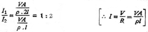
|
| Q.6. |
Calculate the rms value of
the alternating current shown in the
figure. |
| Ans. |
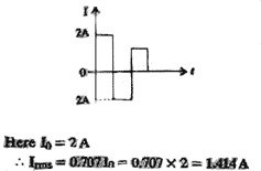
|
| Q.7. |
The image of an object
formed by a lens on the screen is not in sharp
focus.Suggest a method to get clear focusing of
the image on the screen without disturbing the
position of the object, the lens or the
screen. |
| Ans. |
Sharp
image can be obtained by either removing
paraxial rays or marginal rays by using suitable
stoppers.
|
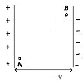
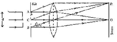
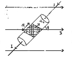
| Q.8. |
Two protons A and B are placed between two
parallel plates having a potential difference V
as shown in the figure. Figure to be pasted.
Will these protons experience equal or
unequal force ?
|
| Ans. |
The two protons will
experience equal force.
|
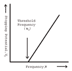
| Q.9. |
Define the terms 'threshold
frequency' and 'stopping potential' for
photo-electricity effect.Show graphically how
the stopping potential, for a given metal,
varies with frequency of the incident
radiation's. Mark threshold frequency on this
graph. |
| Ans. |
Threshold frequency : The
threshold frequency of a metal is the minimum
value of the frequency of incident light below
which the emission of photoelectrons stops
completely. Stopping potential : It is the
minimum value of the negative potential which
should be applied to the anode in a photo cell
so that the photoelectric currents becomes zero.
Figure shows the variation of stopping potential
(V0) with
frequency (v) of the incident radiation for a
given metal.
|
| Q.10. |
Draw labelled diagram of a
leclanche cell. Write the function of charcoal
powder and maganese dioxide used in its porous
pot. |
| Ans. |
Figure
shows the set up of a Leclanche Cell
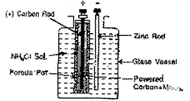
2H+ + 2MnO2 --------------- Mn2O3 + H2O + 2 Units of positive charge
MnO2 acts as the
depolariser while the charcoal powder makes it
electrically conducting.
|
| Q.11. |
How does the mutual inductance of a pair
of coils change when :
- the distance between the coils is
increased ?
(ii) the number of turns in each coil is
decreased ?
Justify your answer in each case.
|
| Ans. |
(i) When the distance
between the two coils is decreased, the mutual
inductance decreases because lesser flux passes
from primary to secondary coil. (ii) Mutual inductance, M =
m N1N2A/l. Clearly when
the number of turns N1 and N2 in the two coils
are decreased, the mutual inductance
decreases. |
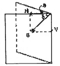
| Q.12. |
Define the terms magnetic
inclination and horizontal component of Earth's
magnetic field at a place. Establish the
relationship between the two with the help of a
diagram. |
| Ans. |
Magnetic inclination (d) :
It is the angle which the direction of total
intensity of earth's magnetic field makes with
the horizontal. Horizontal component of
earth's magnetic field (H) : It is the component
of the earth's magnetic field along the
horizontal direction.
As shown in the
figure, if d is the angle of inclination and H
is the horizontal component of earth's total
magnetic field, then H/B = Cos d or H = B cos d
This is the required relation between d and H.
|
| Q.13. |
An electron in an atom
revolves around the nucleus in an orbit of
radius 0.53 0A.
Calculate the equivalent magnetic moment if the
frequency of revolution of electron is 6.8 X
109 MHz.
|
| Ans. |
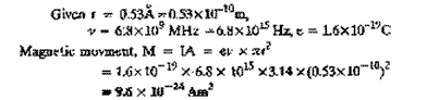
|
| Q.14. |
Write the function of base
region of a transistor. Why is this region made
thin and slightly doped ?
|
| Ans. |
Base
controls the flow of electrons or holes between
emitter and collector. The base is thin and
slightly doped, so that it may contain smaller
number of majority charge carriers. This reduces
the recombination rate of free electrons and
holes in the base region. |
| Q.15. |
Derive an expression for
the energy stored in a charged parallel plate
capacitor with air as the medium between its
plates. |
| Ans. |
Work
done in charging a capacitor. This work done is
stored as its electrical potential energy.
Suppose a capacitor is charged with charge q
snow that potential difference between its
plates is V = q/C Work done to increase the
charge by an amount dq is dW = Vdq = (q/C) dq Total work done to
charge the capacitor from O to Q is W = Q|o q/C dq = 1/C [q2/2]Qo =
Q2/2C Energy of the
capacitor, U = 1/2 Q2/2C = 1/2 QV [ C = Q/Y]
|
| Q.16. |
In the diagram given below
for the stationary orbits of the hydrogen atm,
mark the transitions representing the Balmer and
Lyman series.
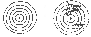
|
| Ans. |
Transitions representing
the Lyman and Balmer scries of a hydrogen atom
are show in the above figure.
|
| Q.17. |
The given figure shows an
inductor L and resistor R connected in parallel
to a battery B through a switch S. The
resistance of R is the same as that of the coil
that makes L. Two identical bulbs, Q and P are
put in each arm of the circuit as shown.
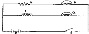
When S is closed, which of the two bulbs
will light up earlier? Justify your answer.
|
| Ans. |
The bulb P lights up
earlier than the bulb Q because the induced
e.m.f. across L opposes the growth of current in
the bulb Q. |
| Q.18. |
Two point electric charges
of values q and 2q are kept at a distance d
apart from each other in air. A third charge Q
is to be kept along the same line in such a way
that the net force acting on q an d2q is Zero.
Calculate the position of charge Q in terms of q
and d. |
| Ans. |
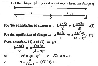
|
| Q.19. |
Explain, with the help of a
circuit diagram, the use of potentiometer for
determination of internal resistance of a
primary cell. Derive the necessary mathematical
expression. |
| Ans. |
The resistance offered by
electrolyte inside the cell circuit is called
internal resistance of cell. Let there be a cell of emf E, internal
resistance r, used to draw current in a circuit
of resistance R. then.
I
= E/R+r
IR
+ Ir = E
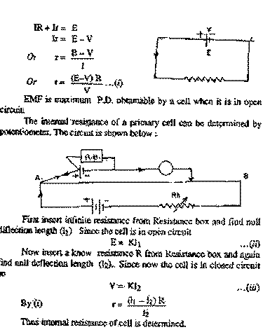
|
| Q.20. |
Sketch the wave-fronts
corresponding to converging rays. Verify Snell's
law of refraction using Huygen's wave theory.
|
| Ans. |
Wavefronts corresponding to
converging to conveying rays are shown in the
figure.
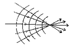
Let the surface AB represent a surface of
separation of two media in which velocities of
light are C1 and C2 respectively.
Let the wave front PQ be incident at an
angle i to the surface AB. By the time Q reached
surface AB at S, the disturbance at P reaches R
such that RS is the refracted wavefront.
The time taken by a ray to travel from T
to U is
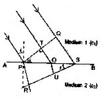
|
| Q.21. |
An electric dipole is held
in a uniform electric field. (i) Show that no translatory force acts on
it.
(ii) Derive an expression for the torque
acting on it. |
| Ans. |
(i) Consider an electric
dipole consisting of charges +Q AND _q and of
length 2a placed in a uniform electric field E
making an angle q with it.
Force an charge =q at B = =q E ( in the
direction of E)
Force on
charge -q at B = - q E ( in the opposite
direction of E)
Total
translatory force on the dipolse = + Q E -Q E =
).
(ii) The two forces acting on the dipole
form a couple. The torque exerted by the couple
is
t
= Either force x Perpendicular distance between
the two forces.
=
QE x AN = qE X 2a sin q
t
= pE sin q
where p = q x 2a, is the electric dipole
moment.
Answer to be inserted.
|
| Q.22. |
Derive an expression for
the width of the central maxima for diffraction
of light at a single slit. How does the width
change with increase in width of the slit.
|
| Ans. |
Suppose a parallel beam of
light falls on rectangular slit AB. According to
Huygen's hypothesis, each point in the slit
becomes a source of secondary wavelets. These
wavelets are initially in same phase and spread
out in all directions.
Cental Maximum : - Let C be the centre of
slit AB. The wavelets which fall on the lens
parallel to CO meet at point O in same phase
because their optical paths between the slit and
the point O are equal. The wavelets add up
constructively and give rise to a central
maximum at O.
Positions of secondary maxima and minima :
Consider point P on the screen at which wavelets
travelling in a direction making an angle with
CO are brought to focus by a convex lens. The
path difference between the extreme rays
starting from A and B is
p
= BN + AB SIN q = d =
SIN
q
where d is width of
slit AB. |
| Q.23. |
capacitor of capacitance
100 mF and a coil of resistance
50 and inductance 0.5 H are connected in series
with a 110 V, 50 Hz source. Calculate the rms
value of the current in the circuit.
|
| Ans. |
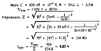
|
| Q.24. |
Draw a labelled ray diagram
to show the image formation in a reflecting type
telescope. Write its two advantages over a
refracting type telescope. On what factors does
its resolving power depend ? |
| Ans. |
Advantages of a reflecting type
telescope. (i) There is no chromatic
aberration as the objective is a
mirror.
(ii) Image is brighter compared to that in
a refracting type of telescope. The
resolving power of the telescope depends on the
aperture of the objective and wavelength of
light used.
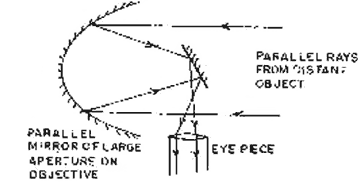
|
| Q.25. |
Define the terms 'solar
constant' and 'solar luminosity'. Explain how
their knowledge helps us to calculate the
surface temperature of the sun. Derive the
necessary mathematical expression.
|
| Ans. |
Solar Constant :
It is defined as the amount of radiant
energy received per second per unit area of a
perfect black body placed on the earth with its
surface perpendicular to the direction of the
radiation from the sun. Solar luminosity : The total
amount of energy radiated by the sun in all
directions per second measured in watt is called
the solar luminosity. It is denoted by
L.
Expression for the surface temperature of
the sun : Imagine a sphere of radius R = 1AU,
with the sun at the centre.
Let S be the solar
constant and r be the radius of the
sun.
According to Stenfan's law, energy
radiated by the sun per unit area per unit
time.
E = sT4, s is Stefan's
constant.
Total energy
radiated by the sun per unit time. =
4pr2 E = 4 pr2 sT4 4 pr2
sT4 = 4 pr2 S
or T4 = R2S/r2s
or T = [R2S/r2s]1/4 |
| Q.26. |
An object is kept in front
of a concave mirror of focal length 15cm. The
image formed is three times the size of the
object. Calculate two possible distances of the
object from the mirror. |
| Ans. |
(i) When the image formed is virtual,
v/u = -3 or v = -3u
As
i/u + 1/v = 1/f
\ i/u - 1/3u = 1/f or 3-1/3u =
1/f
or
u = 2f/3 = 2x(-15) / 3 = -10 cm.
(ii) When the
image formed is real
v/u = +3 or v = 3u
\ 1/3u +1/u = 1/f or 1+3 / 3u = 1/f
or
u = 4f/3 = 4x(-15)/3 =
-20cm. |
| Q.27 |
A voltmeter V of resistance
400 W is used to measure the
potential difference across a 100 W resistor in the circuit
shown here. (a) What will be the reading on the
voltmeter? (b) Calculate the potential
difference across 100 W
resistor before the voltmeter is
connected.
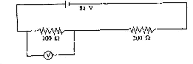
|
| Ans. |
(a)
Effective resistance of voltmeter and 100
W parallel resistor. = 400 x 100/400+100
= 80W
(a) Total resistance
is the circuit, R = 80 + 200 = 280
W
Current in the
circuit, I = V/R = 84/280 = 3/10 A
Voltmeter reading =
80 x 3/10 = 24 V.
(b) Total resistance
before the voltmeter is connected
= 100 + 200 = 300
W
Current in the
circuit, I = 84/300 = 7/25 A
P.D. across 100
W resistor = 100 x 7/25 = 28
W |
| Q.28 |
Derive a mathematical
expression for the force per unit length on each
of the two straight parallel metallic conductors
carrying current in the same direction and kept
near each other. Why do such current carrying
conductors attract each other. OR
Derive a mathematical expression for the
force acting on a current carrying straight
conductor kept in a magnetic field. State the
rule used to determine the direction of this
force.
|
| Ans. |
AB and CD are two
infinitely long conductors, placed parallel to
each other, and separated by distance. The
currents through them are I1 and I2
respectively. Magnetic field at distance
from AB is B1 =
m0I1/2pr This magnetic field
acts perpendicular to CD and into the plane of
paper. Force per unit length of conductor CD
is
f = B1
I2 . 1 =
m0I1/2pr X f2 X 1 = m0I1/2pr By Fleming’s
left hand rule this force acts as CD towards AB.
The conduct AB also experience the same force
towards CD. Hence there is attraction between AB
and CD.
OR Consider a straight
conductor PQ of length l, area of cross -
section. A carrying current I placed in a
uniform magnetic field ®B. Suppose the
conductor is placed along x-axis and magnetic
field acts along y-axis. Current I flows from
end P to Q and electrons drift from Q to
P.
Let ® vd = drift velocity of
electron. |
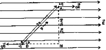
| Q.29. |
Draw a labelled diagram of Thomson's
experimental set-up to determine e/m of
electrons. Explain, by deriving the necessary
mathematical expression, how e/m of electrons
can be determined by this
method. |
| Ans. |
(a) Thomson set up for the
determination of e/m of electrons in the figure
below
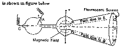
Now potential energy of electrons at the
cathode = eV
Kinetic energy of an electron at the anode
= 1/2mv2
By law of conservation of energy, 1/2
mv2 = eV
So the velocity of electrons,
n =
(2eV/m)1/2
b) E = V/d
\
e/m = E2 / 2VB2 = V2 / 2VB2 d2 = V/2B2 d2
As d is fixed ,
therefore,
B2 µ V or B
µ (V)1/2
If V is doubled,
then
B'/B' = (v)1/2 / (v)1/2 = (2v)1/2 / (v) 1/2 = (2)1/2
or B' = (2B)1/2
So magnetic field
should be increased to (2) 1/2 B to keep the electron beam
undeflected.
Theory : Let E be
the intensity of electric field then the
electron will experience a force F1 in upward
direction
F1 = Ee
Let B be the
intensity of magnetic field. The electron moving
with velocity n will experience a
force Ben in the direction
opposite to that in electric field.
F2 = Ben
If the electric and
magnetic fields are so adjusted that the
electron beam undergoes no deflection, then
Ben
=Ee
Or n = E/B
If V be the
accelerating voltage applied between the cathode
and anode, then
Ve = 1/2
Mn2
or e/m = 1/2
n2/V
= 1/2 E2 / B2 V
Knowing the value of
E, B and V, the value e/m can be determined.
|
| Q.30. |
Define the terms 'potential barrier' and
'depletion region' for a p-n junction. Explain,
with the help of a circuit diagram, the use of a
p-n diode as a full wave rectifier. Draw the
input and output wave-forms.
|
| Ans. |
Potential Barrier : This is the
potential difference established across the p-n
junction due to diffusion of electrons from
n-region to p-region and holes from p-region to
n-region. Depletion
region : It is a thin layer formed
between p - and n-sections which is devoid of
free electrons and holes and has only immobile
ions.
A
full wave rectifier uses two diodes as shown in
Fig.
Figure to be inserted.
Let the point A of transformer be positive
during first half of the input cycle. The
voltage decreases as we move from A to C.
Obviously the point A is at higher potential
with respect to B. the anode of diode D1 is positive with
respect to cathode and it conducts. The
direction of current flow is shown by solid
arrow. The diode D2 is reversed biased so does not
conduct. During the second half cycle let C be
at positive potential relative to A, then diode
D2 will conduct
and not the diode D1. The direction of current is shown
by dotted line. It is clear from the figure that
during both halves the current through load
resistance RL is
unidirectional. Since there is an output during
both halves of the input signal, the output also
is continuous. The input and output signals are
shown below.
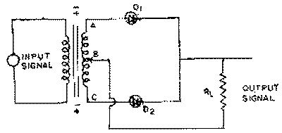
|
